Rasters
There is enough material written about difference in Local Scene versus Global Scene (Choose global or local—ArcGIS Online Help | Documentation). Here I will be using Local Scene as I am in a particular area. The new Local Scene just got create with default layers in the table of contents:
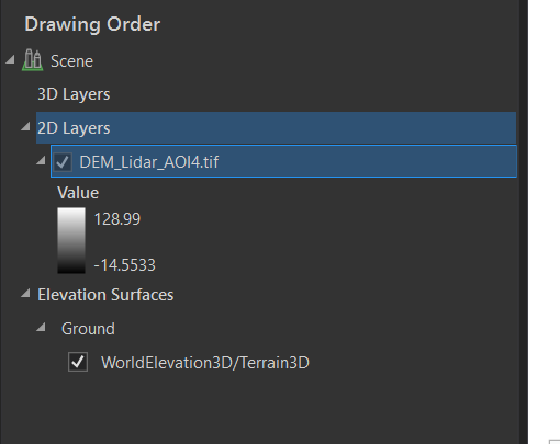
3D layers – that would be a vector data enabled with elevation values (in the attribute tables types would change from regular points, lines, polygons to zpoint, zpolyline, zpolygon).
2D layers – vectors without 3D values enabled and rasters. Important to point that even if you do have elevation rasters – they WILL NOT be treated as 3D instantly.
Elevation Surfaces – this group hold Grounds and custom Surfaces. By default the World Elevation data is used as a source of the Ground. Elevation Surfaces define elevation values of the surface in the area of the project. This is the part that needs to be customized.
Read more about Elevation Surfaces here – Elevation surfaces—ArcGIS Pro | Documentation.
There are two things to keep in mind here – Ground Elevation and Elevation Surface. Ground elevation determines general elevation in the area, it can never be removed, but default World one could be replaced with more detailed local data. This is the primary reference piece from which elements could be offset upward or downward.
Step 1 – Adjusting Ground Elevation references
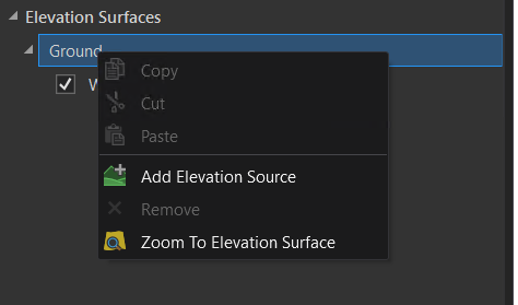
Option 1 – Right-click on Ground to add a new elevation reference data;
Option 2- grab elevation raster from the 2D group and drag it under Ground;
Option 3- On the Map tab, click Add Data – select Elevation Source – navigate to location of your elevation raster;
Adjust general properties for the Ground. For that, select Ground to activate a new tab in the Ribbon.
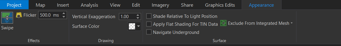
Turn Surface Color to None – this would allow to see items underground.
Vertical Exaggeration – allows to extrude features for a more dramatic visual. This works better for flat areas.
Step 2 – Create Surface
Elevation Surfaces is another elevation reference. I am yet to find a good explanation on the exact difference between the Ground and the Surface. One thing I can add here is that if another raster has to be draped over and display terrain highs and lows – that is where custom surfaces come into play.
One of the examples where surfaces could be used – bringing subsurface information at different depth levels. In the past I would create a custom surface using a raster (enabled with negative values if subsurface), then drape the same subsurface raster over the new surface. Basically, a subsurface raster would drape over itself as a surface.
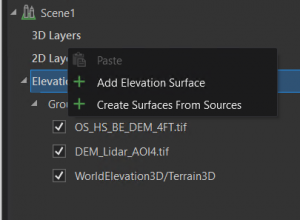
First, let’s create a custom surface. Right-Click on Elevation Surfaces Group, select Add Elevation Surface. A new blank group will be added to host surfaces (here it will be called Surface 1).
Now, right-click on the newly created Surface 1 group – select Add Elevation Source. Navigate to location of the raster.
Step 3 – Drape raster over custom Surface
So, Ground references are established, custom Surfaces are created, now it is time to display a raster properly in 3D.
Make sure the raster you want to display in 3D is loaded into the Scene. It will reside under 2D layers. Right-click on it, go Properties. There should be two options here – On the ground and On custom elevation surface.
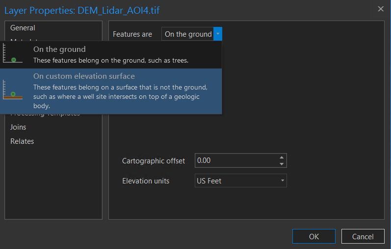
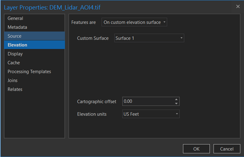
Here, select On custom elevation surface. Point to the newly created Surface as a reference to. This what the properties should look like:
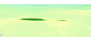
2D raster is now drapes over custom surface producing a 3D effect.
Let’s say for example, you got several rasters at different depth. You would want to bring them stacked one above the other. You can do so by using those rasters to create several surfaces, each reflecting values at a different depth. Then drape each raster over itself.
Vector
When working with vector data, it is important to prepare it just right for the data to extrude in 3D. It is worth mentioning though that with the latest version of ArcPro (here 2.8.1) a lot of work got much simplified. Choose one of the following options to create 3D from a vector:
Option 1 – 2D feature layer has elevation values as part of the attribute table. Columns could be setup to indicate the height of the feature, and the height above ground to which the feature would be lifted up to.
Example, facilities sit on top of a pad. The pad is 5 feet high. A building is 12 feet high and sites on top of the pad. Therefore, that building is 5 feet off the ground. So, one columns in the building’s attribute table would have building height (12-ft), and the other one would have the offset (5 feet).
Option 2 – create a multipatch from the vector. Instructions on how to create a multipatch could be found here – Create multipatch or 3D Object features—ArcGIS Pro | Documentation.
This video shows working with multi-patches
Option 3 – have a 3D vector data.
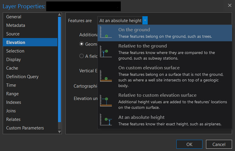
Let’s take a look at a 3D feature added to already created project with established custom surfaces and the ground. If a vector is 3D enabled it will be added to the 3D group in the table of contents. Right-click on it to go into Properties – Elevation. Since both the Ground and Surfaces are enabled, several reference options are now available:
This article explains these types pretty well – Define height characteristics for layers—ArcGIS Pro | Documentation
For a layer created using field topographical survey data and enabled with appropriate height information, use Absolute Height option. This will place the feature on the ground, and use embedded elevation values to draw it in 3D.