Never was DEM creation that straightforward in ArcGIS as it is in Global Mapper. And in both cases processing the data should be done carefully as to preserve elevation information in the new raster as accurate as possible.
I will try to review available options. First of all, I would avoid Interpolations tools in the 3D Analyst Toolbox simply because one must really understand how those interpolations work. If you are not that kind of expert – go for something simpler.
I have .xyz file with point data containing survey information. Note, that ArcGIS does not recognize .xyz format. However, Global Mapper does. I will try creating elevations in both environments.
ArcPro
Step 1 – Create point data
The .xyz file will most likely contain a top portion with additional information about the project, coordinate system, etc.
Open Excel, go to Data tab – select From Text/CSV (make sure All Files (*.*) is selected to see the XYZ file). Load the data. Before loading, transform it by removing unnecessary information and making sure correct headers are assigned. Save Excel file.
Open ArcPro. Create a new map if not have done so.
- Assign correct Coordinate System to the map (based on what the data was collected and delivered in)
- Assign correct vertical reference. Note, that for the bathymetry data it might be in National Ocean Service (NOS) Mean Lower Low Water (MLLW). For the ground data, NAVD88 unless otherwise specified in the deliverable.
- On the Map tab, click “Add Data”, select ‘XY Point Data”
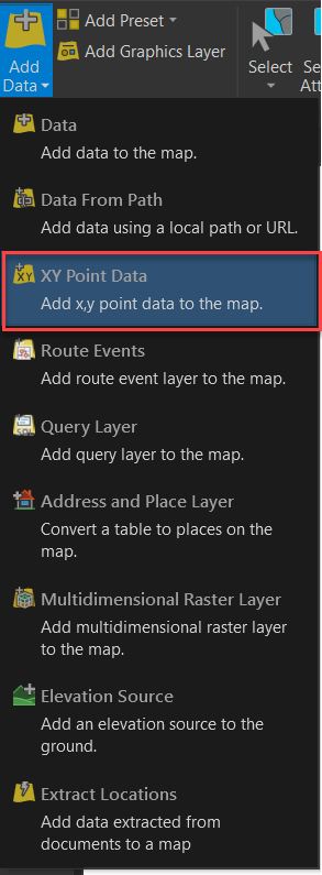
Don’t forget to grab Z values. Finished results would display collected point data.
Step 2 – Create Triangular Irregular Network (TIN)
TINs like anything, do require some understanding on how the interpolation works. More about TINs here – TIN in ArcGIS Pro—ArcGIS Pro | Documentation.
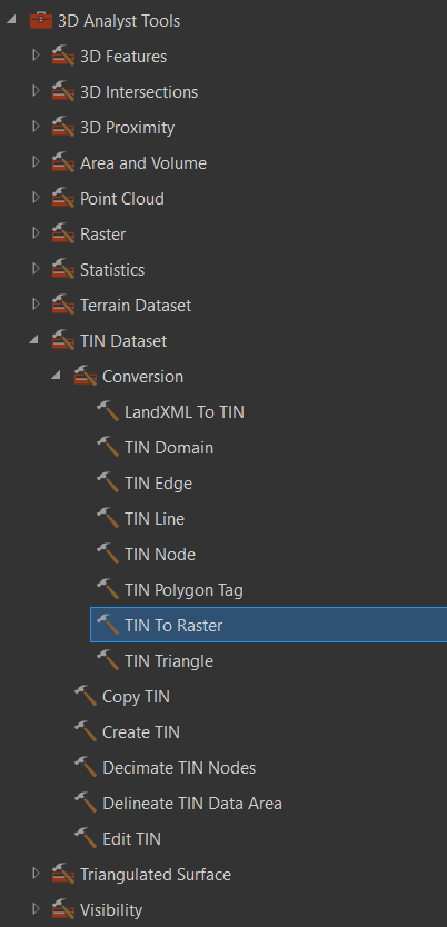
The tool to create TINs requires 3D Analyst extension and is located here:
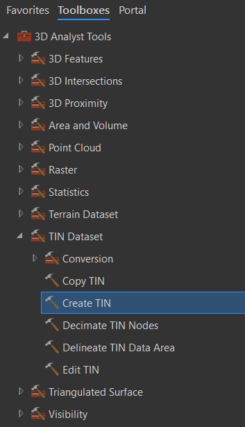
Don’t forget to grab Z-value field and add it to “Height Field” when running the tool. Here I will also check the “Constrained Delaunay” box. Created TINs are always a bit unnerving at first since they could look weird enough.

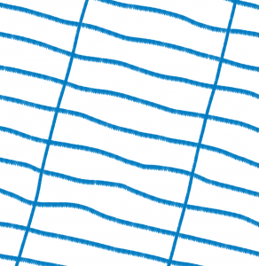
In this case, original data was a series of points collected along spaced far apart transects. But no matter for now, as this is a transition step.
Step 3- Run TIN To Raster
Additional Sources:
- TIN to raster conversion (cuny.edu)
- TIN To Raster (3D Analyst)—ArcGIS Pro | Documentation
- How TIN To Raster works—ArcGIS Pro | Documentation
TIN To Raster is another 3D Analyst tool located here:
For this exercise I choose “Cell Size” for Sampling Distance. For the Method – I pick “Natural Neighbor”. This interpolations produces smoother results. here is the comparison between (A) Natural Neighbor – Cell size and (B) Linear Method – Observations and Sampling Distance:

(A) – Natural Neighbors method – Cell Size sampling distance (value 10)

(B) Linear method – Observations as sampling distance (default 250 value)
NOTE: There is something important to remember. If you have general area in an irregular shape, obtain area boundary prior to running raster creation. In that case, under Environments it is possible to specify the Extent and set it to the boundary. Otherwise, created raster will fill in some areas.
For example, you have a topo survey data around an area with structures (gated compound for example). That area was not surveyed and you don’t want it to be part of the new elevation raster as it won’t contain actual survey data. Without masking that area, the tool will interpolated and fill in the space.
Global Mapper
Now, let’s try the same in the Global Mapper.
Step 1 – Create Point data
(same as step 1 for ArcPro).
Step 2 – Add point data to Global Mapper
I made a shapefile in ArcPro from the imported XYZ coordinates. So, I can just open that one in the Global Mapper.
Step 3 – Created Elevation Grid
Located the tool in the toolbar under Analysis group:
![]()
Here is the tool interface:
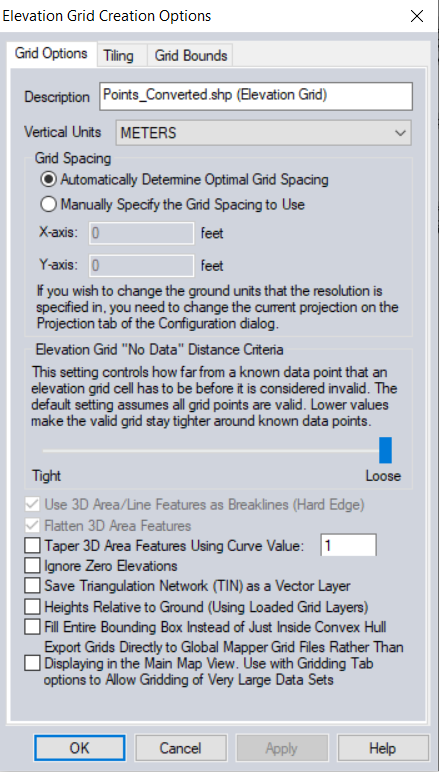
Pay attention to Vertical units, to make sure they are consistent with the format of the provided survey data.
Just like the ArcPro, the Global Mapper will interpolate any spaces in irregular areas, or will interpolate to the bounding box of the area if you check that option (effectively creating a square or a polygon around the irregular shaped area).
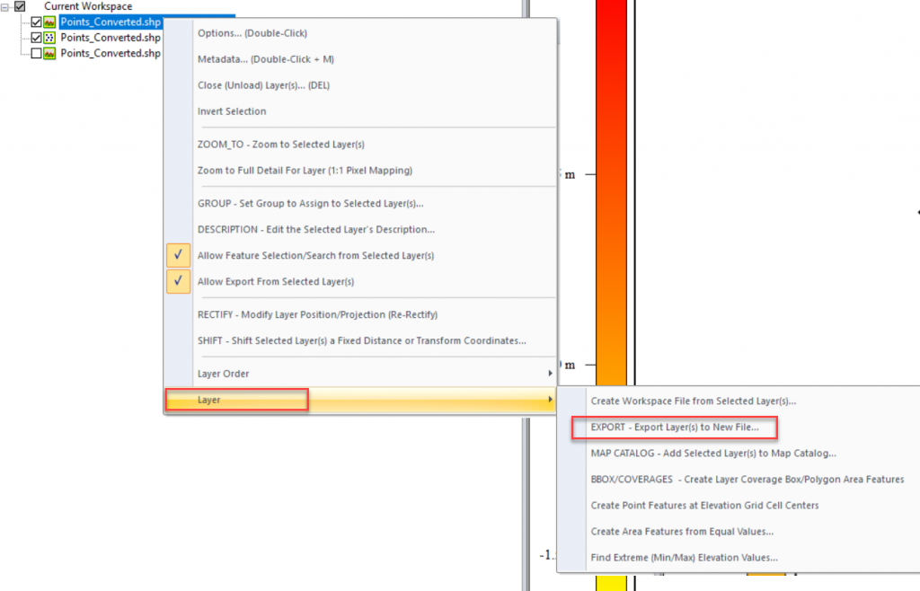
Step 4 – Export
Created Elevation Grid will only stay within the Global Mapper opened workspace. Unless it is exported as a file. To export, Right-click on the grid – Layer – EXPORT.
There is a wide variety of file types available to export into. Select the one based on your needs.
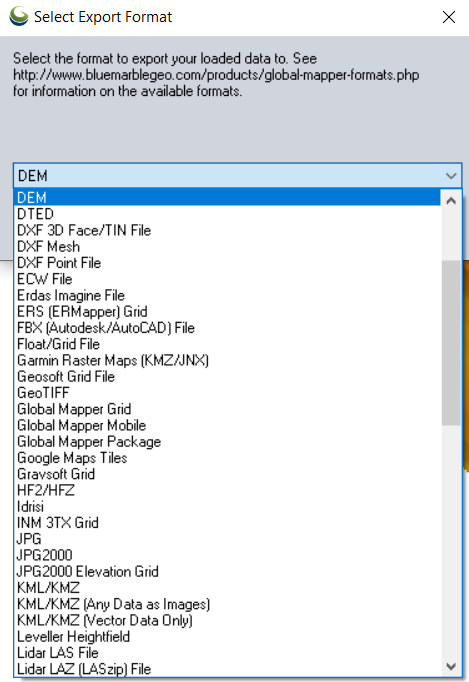
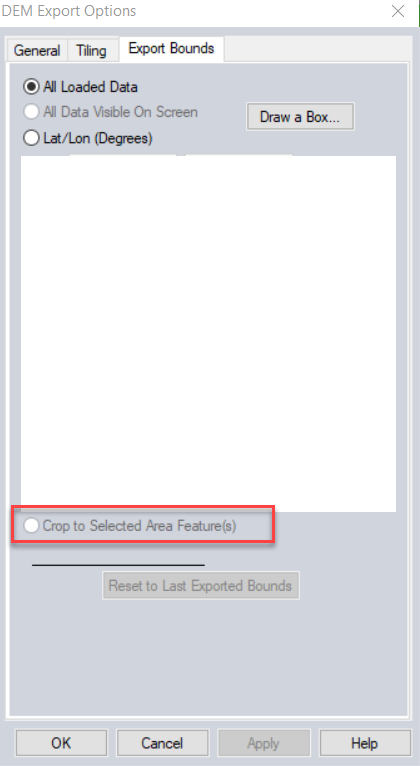
I will try DEM here. I do want to crop the area to a specified boundary. That option is available only if the boundary is loaded and selected within the workspace prior to the export. Use Digitizer tool (looks like a pencil) or Alt+D to select.
If the boundary is loaded and selected, there will be a checkbox option called “Crop to Selected Area Feature(s)” available under Export Bounds tab.